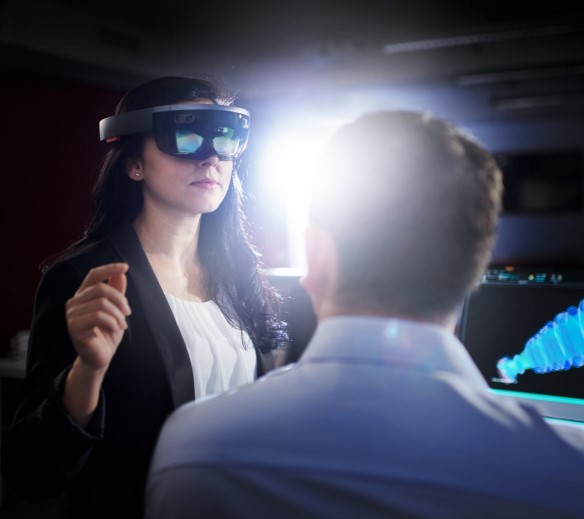
AR/VR
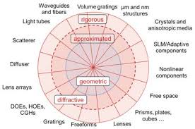
Maxwell solver solutions
connected through
non-sequential field tracing
connected through
non-sequential field tracing
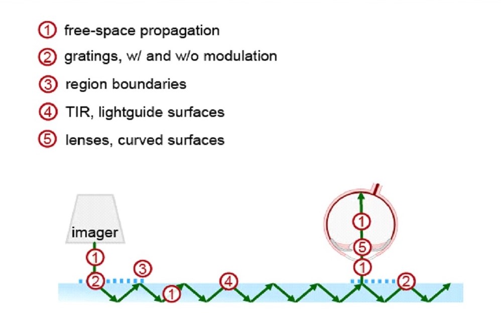
propagation regions in light guide
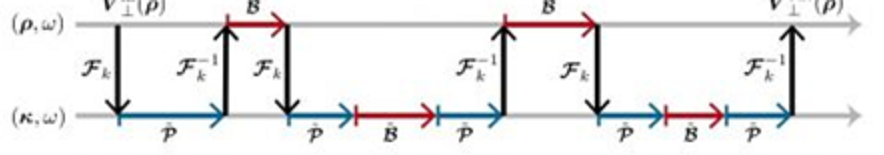
switching between
spatial domain (x-domain) and
frequency domain (k-domain)
in regions along the lightpath
spatial domain (x-domain) and
frequency domain (k-domain)
in regions along the lightpath
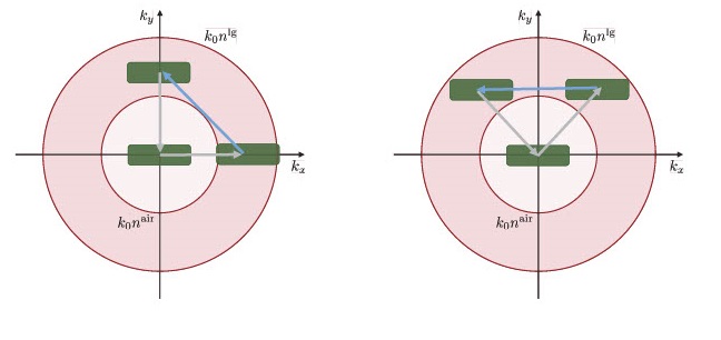
Two K-Diagrams
showing FOVs for two
possible light guide layouts
showing FOVs for two
possible light guide layouts

FOV source modes
spectral modes
polarization modes
spectral modes
polarization modes

light guide
incoupling source FOV
outcoupling eyebox FOV
and eyebox uniformity
incoupling source FOV
outcoupling eyebox FOV
and eyebox uniformity

psf mtf
Light Guide simulation, design and optimization
for augmented reality and virtual reality applications
for augmented reality and virtual reality applications
Light Guide Toolbox, and
VirtualLab Fusion Advanced -
includes FMM/RCWA for rigorous grating analysis
VirtualLab Fusion Advanced -
includes FMM/RCWA for rigorous grating analysis
The VirtualLab Light Guide Toolbox is for modeling light guide display systems for AR/VR and HUD applications.
There are two versions of the Light Guide Toolbox: Silver and Gold.
Silver is for simulation, while Gold includes simulation, design and optimization.
Both versions work along with and require VirtualLab Fusion Advanced, which includes the Starter Toolbox, Grating Toolbox, and Non-Sequential Extension. The Grating Toolbox in VirtualLab Fusion Advanced, includes rigorous modeling of gratings by Fourier Modal Method (FMM), which is also called Rigorous Coupled Wave Analysis (RCWA).
The goal of the Light Guide Toolbox is to simulate, design and optimize light guide image quality, given the tradeoff between uniformity and system efficiency, while also considering field of view (FOV) and multiple wavelengths.
The physical optics modeling in the Light Guide Toolbox shows the effects of polarization, interference, diffraction and temporal coherence.
The Light Guide Toolbox connects multiple physical optics solvers, along with multiple freespace propagation methods, all on a single platform
For fast and accurate physical optics modeling of electromagnetic fields, calculations are either in the spatial domain (x-domain) or frequency domain (k-domain). Fourier Transforms and inverse Fourier Transforms switch between the x-domain and k-domain for the most efficient calculation method in each region of the lightpath.
This enables the VirtualLab Light Guide Toolbox to couple multiple gratings and other optical elements along the lightpath for system modeling and parametric optimization.
Light guide layout
- K-domain calculator for maximizing FOV
Calculator entries include...
- wavelength
- desired FOV width angle, height angle and offsets
- incoupling grating parameters
- eye pupil expander grating parameters
- outcoupling grating parameters - K-Diagram shows light guide layout FOV limits graphically
....see two K-Diagram layout examples on left
Source Modeling
- Source modeling can include all imager optics
- FOV modes for each wavelength
- Temporal coherence per wavelength
- Dispersion per wavelength
- Polarization modes per spectral mode
Detectors for input, inside light guide, output
- "Footprint" detector: zig zag path and size of beam
- Electric field detector: amplitude of Ex and Ey energy density
- Intensity detector
- Polarization detector: local state of polarization
- Custom detectors: such as photometric and radiometric
The ultimate goal of the Light Guide Toolbox is producing quality image spots for all FOV angles and any position in the eyebox.
Optimization merit functions
- Radiant Flux (watts)
- Luminous Flux (lumens) into to eye pupil
Position dependent flux compensation requires eye tracking. Lumens per FOV angle can be controlled by the imager. This can help control non-uniformity over FOV angles.
Non-uniformity can be also addressed by shaping the incoupling efficiencies over the FOV. - 2D MTF: Such as: resolution for 50% contrast in a specific direction
- Custom merit functions for specific scenarios
Optimization design parameters
- Selection of light guide refractive index and thickness
- Location of grating regions
- Imager: bandwidth, beam size, polarization
- Binary grating: aspect ratio and height
- Slanted grating: height and slant angle
- Volume grating: index variation range
- Initial average outcoupling efficiency into working orders
- Local modulation of grating parameters within regions